 |
10. TOMOGRAPHY |
10.1 Overview |
Tomography is a method for reconstructing the interior of an object from its projections.
Especially the term electron tomography is used for any technique that employs the
transmission electron microscope to collect projections of an object and uses those
projections to reconstruct the object in its entirety ( overview in [1] ).
The automated electron tomography (AET) is a technique for automatic acquisition of a tilt series
with tilt induced displacement cottection. As the displacement has components in X, Y and Z
direction, the image has to be shifted back and the focus has to be readjusted. The lateral displacement
is measured by cross-correlating an image with an previosly recorded reference image and corrected
using the image shift facility of the microscope. For compensation of very large displacements corrections
are performed in lower magnifications. For the focus adjustment the autofocus procedure developed by
Koster et al.[4] is used.
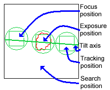
For low dose imaging 5 different specimem positions ( areas ) are used:
| Position | Meaning | Location *) | Magnification |
|---|---|---|---|
| Exposure | image of interest | centered | high |
| Search | rough displacement correction | centered | low |
| Focus | focus correction | besides, along tilt axes | high |
| Tracking | fine displacement correction | besides, along tilt axes | high |
| Scanning | scratch | not used during acquisition | current |
*) relative to the detail of interest.
Generally the positions will be aligned as shown below. To fulfil low dose conditions the condensor should be adjusted to illuminate only the circular area around the corresponding position.
 |
The following list gives an overview of the ( idealized ) data acquisition procedure.
For more details see the following references:
[1] Electron Tomography, Edited by Joachim Frank (Plenum Press, New York, 1992 )
[2] K. Dierksen, D. Typke, R. Hegerl, A.J. Koster, W. Baumeister: Towards Automatic Electron Tomography, Ultramicroscopy 40 (1992 ) 71-87
[3] W. Hoppe, R. Hegerl in: Computer Processing of Electron Microscope Images, Topics in Current Physics, Vol.13, Ed.P.W. Hawkes (Springer, Berlin,1980) p.127
[4] A.J. Koster, D. Typke and M.J.C. de Jong: Fast and accurate autotuning of a TEM for high resolution and low dose electron microscopy,Proceedings of the XIIth International Congress for Electron Microscopy 1990
10.2 Start |
The 'Positions' dialog is opened with ![]() .
.
 |
The 'Position' dialog consists of the following sections
10.3 Calibration |
With a click on ![]() in the positions dialog the calibraion dialog will be opened.
in the positions dialog the calibraion dialog will be opened.
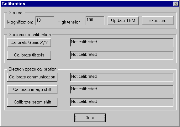 |
The calibration is necessary for most of the other operations performed on the positions. It is at least necessary to execute the calibration for
all the magnification / high tension combinations you will use. To calibrate, insert a specimem with a good contrast to receive better cross-correlations.
Select the desired magnification on the TEM, then click ![]() and
and
![]() to check whether you have "something" good correlating visible.
to check whether you have "something" good correlating visible.
Click the CALIBRATE XXX buttons from top to bottom and follow the instructions. Some calibrations need some time, while others are fast, some need user interaction, some not. If a calibration has been performed successfully, the field right to the corresponding button is filled with the date and time of the calibration as well as with calibration dependent data.
Note: A 512*512 image format is sufficient for the calibrations. It has also the advantage of a higher calibration speed ( compared to 1024*1024 or 2048*2048 image format ) due to drastically shorter computation times e.g. for cross-correlation ( 1 cross-correlation requires besides other operations: 2 forward FFTs and 1 inverse FFT ).
| Calibration | Comment |
|---|---|
| The goniometer x and y shift are calibrated. This calibration can take a few minutes. The result angle should be near 90 degree ( or 270 degree ) and the ratio should be near 1.0 | |
| The tilt axis angle relative to the CCD image x axis is calibrated. This is very fast. Note: You will receive the best results ( both for the tilt series acquisition algorithm and the reconstruction ) if the camera is mounted in such a way that the tilt axes angle is (near) 0 degree for the magnification used for the EXPOSURE position, i.e. you will possibly have to turn your camera. |
|
| The ratio between the changes in ticks of e.g. beam shift, illumination, etc. and their internal TEM data representation is calibrated. On most TEMs this is 1:1, but some use a 1:2 or other ratios. This calibration is very fast. | |
| The image shift is calibrated. This can take up to 1 minute. | |
| The beam shift is calibrated relative to the image shift. User interaction is required. Follow exactly the orders in the dialog boxes when they appear. It is not necessary to minimize the radius of the beam to a spot. |
10.4 Position handling |
The 5 different positions ensure that there is not too much dose on the specimen's area of interest. There is a position for the area of interest
( EXPOSURE position ), for focussing ( FOCUS area ), coarse displacement correction ( SEARCH position ) and fine displacement correction ( TRACKING
position )
The chapters 10.4.x describe how to work with those 5 positions.
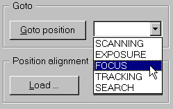
To go to to a position means: Reload the last used settings of that position and treat this position as current position. To go to a position, select the desired position in the dropdown dialog element, then click the Goto position button.
 |
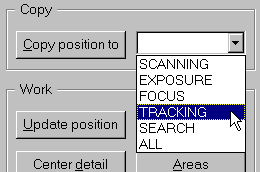
To copy the current settings into the settings of a specific position, select the desired position in the corresponding dropdown element, then click the Copy Position button. To copy the current settings into the settings of all positions, select ALL in the dropdown element.
 |
 |
The 'Show positions' dialog both enables to monitor the position settings and change the settings by hand. The left half of the dialog is for information only and to compare corresponding settings of the different positions. To change entries of a specific position, click on the corresponding tab to select the position, change the value(s) in the edit fields, drop down elements or radio buttons and click Apply or OK.
The following data can be changed:
The 'Show positions' dialog is opened with a click on ![]() in the 'Positions' dialog.
in the 'Positions' dialog.
A click on ![]() reads the current EM settings and stores it into the setting data of the current
selected position.
reads the current EM settings and stores it into the setting data of the current
selected position.
Note: The camera settings of the positions are not changed.
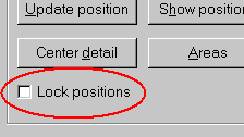
Before starting the centering of the detail of interest, check whether you want to lock the positions or not. Locking of positions means that if one position is moved, all the other positions are moved accordingly as if they are connected. To lock the positions check the option 'Lock positions' in the 'Positions' dialog. If this option is not selected, 'Center detail' will only influence the currently selected position.
 |
 |
After clicking OK the position settings for the image shift are adapted in such a way that the detail of interest will be visible in the center of the image. To verify that an additional exposure is taken and displayed.
Even it is possible to select the positions for EXPOSURE, FOCUS and TRACKING individually, a powerful tool is available. This tool is only available
in SCANNING position. The 3 positions are displayed as squares where the edge sizes are defined by the ratios of the magnifications of the 3
positions to the magnification of the SCANNING position. Also the tilt axis is drawn.
Note: Every time the Areas tool is started, the 3 positions will be set to the default positions, i.e. all the previous settings
are lost. This is to avoid positions out of the SCANNING position and with that out of the display screen.
Clicking on ![]() will take an exposure and suggest settings for EXPOSURE, FOCUS and TRACKING positions.
Then the 'Areas' dialog will open.
will take an exposure and suggest settings for EXPOSURE, FOCUS and TRACKING positions.
Then the 'Areas' dialog will open.
 |
The 'Areas' dialog provides 3 sections for user interaction:
 |
Note: Due to dose problems for some specimems the positions should not overlap.
Clicking on ![]() or
or ![]() opens the file selector
dialog where you have to specify the filename. The position settings will be loaded from this file or written to this file, respectively.
opens the file selector
dialog where you have to specify the filename. The position settings will be loaded from this file or written to this file, respectively.
Note: If the settings are loaded from file, the current settings are "overwritten", i.e. the microscope settings of the
current position are sent to the microscope. E.g. EXPOSURE is current position and the settings are loaded, then after loading is finished the settings
of the EXPOSURE position in the file will be the current settings now. That also means that the beam shift and the image shift are probably changed.
Both buttons ![]() and
and ![]() are used to check
the quality of the position settings. Exposure takes an exposure with the current position settings and Power computes the power spectrum
of the last exposure.
are used to check
the quality of the position settings. Exposure takes an exposure with the current position settings and Power computes the power spectrum
of the last exposure.
10.5 Positions: step by step |
This is a short "recipe" how to define the positions for a standard tomography session:
10.6 Tilt series |
A click on ![]() starts the 'Tilt series' dialog:
starts the 'Tilt series' dialog:
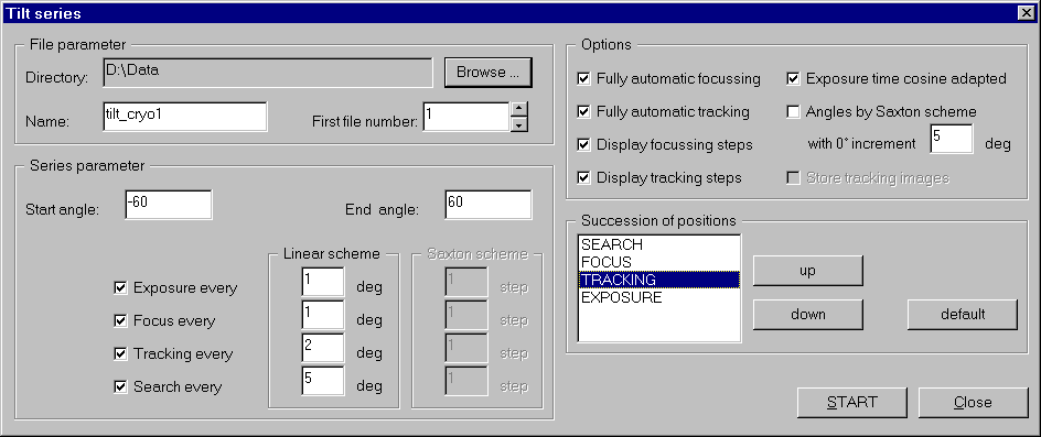 |
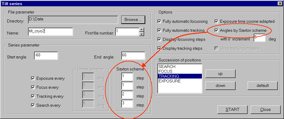
The 'Tilt series' dialog consists of 4 sections:
 |
A click on ![]() generates the position flow for the tilt series acquisition out of the specified
parameters and options. The result is displayed in the 'Tilt series exposure map' dialog.
generates the position flow for the tilt series acquisition out of the specified
parameters and options. The result is displayed in the 'Tilt series exposure map' dialog.
 |
The 'Tilt series exposure map' dialog displays in its left half the indexed positions as they will be executed during the acquisiton. Here you can see how the tilt series acquisition will work. In the dialog displayed above, the algorithm will
Here you have the (last) change to modify the succession of positions. You can delete one or more positions, swap positions and add entries:
A click on ![]() starts the new series.
starts the new series.
10.7 Saxton scheme |
The saxton scheme ensures that you have equidistant sampling points in the three-dimensional fourier space. In the real space you can see the criterion displayed in the figure below:
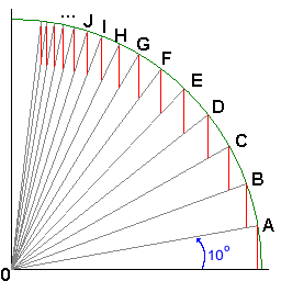 |
Starting with an angle of alpha ( here in this example: alpha = 10 degree ) against the x-axis defines the size h of the red vertical line as
h := r * sin(alpha), where r is the radius.
The next angle is defined by the following constraints: The red vertical line with fix size h sits on the line OA and ends at the circle line and defines B.
The angle between x-axis and OB is the new angle.
In that manner all the (infinite number of) angles are constructed. (Infinite, because it will never reach 90 degrees ).
With this algorithm and an start angle of 10 degree the first 19 angles ( besides 0.00000 degree ) are:
If e.g. the tilt series start angle is -70 degree and the end angle is +20 degree and the 0 degree increment is 10 degree, the following angles are used:
10.8 Semi automatic mode |
Either by pressing the SPACE key during the tomography or by not selecting the Fully automatic tracking option in the 'Tilt series' dialog, the tilt series acquisition will switch into the semi automatic mode. Semi automatic mode means that no automatic fine or coarse displacement correction is performed in the TRACKING or SEARCH position, respectively. Every time TRACKING or SEARCH has its turn, the 'Semi automatic dialog will open.
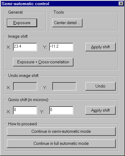 |
The 'Semi automatic' dialog provides all the possibilities to perform coarse and fine displacement corrections.
After the displacement corrections you can decide how to proceed
| Stay in semi automatic mode, i.e. the next time the turn is on TRACKING or SEARCH, this dialog will open again. | |
| Continue in full automatic mode, i.e. this dialog will no more open unless the SPACE key is pressed. |
10.9 Spotscan |
A click on ![]() in the positions dialog opens the spotscan dialog.
in the positions dialog opens the spotscan dialog.
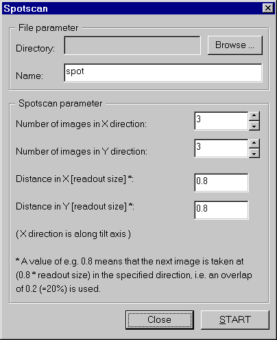 |
Enter the directory and filename to save the spotscan images in the section 'File parameter'.
Also enter in the section 'Spotscan parameter' the values for the number of images in X and Y direction as well as the desired corresponding overlap of the images.
Note: Check that the goniometer tilt angle is set to zero, otherwise the spotscan procedure will fail.
Note: The calibrations for the current magnification/high tension must be available.
The spotscan procedure will acquire the desired number of images where the current image will be the central image, if the number of images is odd. You can use the tiling procedure to merge the images.Last update: